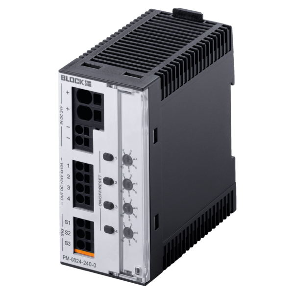
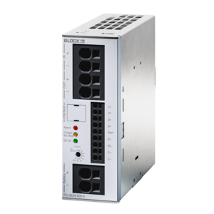
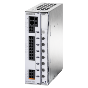
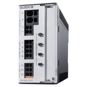
4-Channel circuit breaker
PM-0824-240-0
Characteristics
Benefits
› Adjustable tripping current for each output channel via current selector switch
› Selective immediate switch off of defective circuits in the event of critical supply voltage
› Sequential and load-dependent switching-on of channels
› Comprehensive single-channel-diagnostics and remote switching on/off of each output channel via 2-wire-interface
› Further diagnoses of input voltage and the current of each circuit
› Group alarm contact
› 3 years warranty
| Product | 4-Channel circuit breaker |
| Order number | PM-0824-240-0 |
| Series | BASIC SMART |
Input
| Rated input voltage | 24 Vdc |
| Input voltage range | 18 Vdc to 30 Vdc |
| Max. continuous current of the module | 24 A |
| Max. continuous current feed terminal (+) | 40 A |
| Max. ripple of the feeding input voltage | 3 % |
| Switch-on threshold | 19.50 V |
Output
| Rated output voltage | 24 Vdc |
| Rated Output Current | 6 A |
| Rated Output Current Adjustable | 0.5,1,2,3,4,6 |
| Rated Output Current per Output Channel | 6 A |
| Output voltage range | 24 Vdc |
| Number of Output Channels | 4 |
| Switch-off threshold | 18 V |
| Max. voltage drop between input and output | 145 mV |
| Max. power loss | 4.3 W @ 4 x 6 A |
| Max. waiting time after switching off an output after an overload (thermal relaxation) | 20 s |
| Idle current @ 24 V | 32 mA |
| Max. feedback resistance | 35 Vdc |
| Power losses in stand-by mode | 0.77 W |
| Parallel connection of outputs | Not allowed |
| Series connection of outputs | Not allowed |
| Release Characteristics | Active current limiting |
Signaling
| Signal output S2 | 24 Vdc, max. 25 mA (status output channels) |
| Signal output S3 | 24 Vdc, max. 25 mA (Common signalling output) |
| Status display | Green, yellow, red LED |
Environment
| Climate class according to EN 60721 | 3K3 |
| Ambient temperature | -25 °C to 70 °C / -13 °F to 158 °F |
| Storage temperature | -25 °C to 85 °C / -13 °F to 185 °F |
| Humidity without condensation | 5 % to 96 % |
| Cooling type | natural convection |
| Required minimum distance (side) | 0 mm |
| Required minimum distance (top/bottom) | 40 mm |
Protection and Safety
| Degree of pollution | 2 |
| Protection class according to EN 61140 | III, without PE connection |
| Safety extra low voltage (SELV/PELV) | IEC 60364-4-41 (DIN VDE 0100-410) |
Size and Weight
| Width | 45 mm / 1.77 in |
| Height | 90 mm / 3.54 in |
| Depth | 91.5 mm / 3.6 in |
| Depth incl. DIN TH35 | 97.5 mm / 3.84 in |
| Weight | 0.2 kg / 0.441 lbs |

