
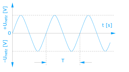
The ambient air temperature for measurement is the highest ambient air temperature at which a piece of electrical equipment or an electrical device or an installation component (e.g. transformer, reactor, filter) can be operated continuously under normal operating conditions. It is the air temperature of the immediate surroundings. Electrical values often refer to the ambient air temperature for measurement and they can change with different temperatures! Special attention is to be paid to the installation of components in housings with a higher type of protection. Possible deficient cooling can lead to non-authorised high temperatures in the housing. A reduction of the expected service life of the component is possible in this case (see “Insulation material class”).
The ambient air temperature for measurement is specified using a shortened notation form (Ref.: VDE* 0570, EN 61558, IEC 61558).
Example:
ta = 25 °C or ta = 40 °C
Unless other arrangements have been made, the rated ambient temperature used for the design of components intended for installation is set at 40 °C and at 25 °C for (table) devices which are to be operated independently.
*Association of german electrical engineers
Auto transformers are transformers in which input and output coils share common parts (Ref.: VDE 0570 Parts 2–13). For this reason, there is no metallic isolation between the coils.
Requirements:
The general statements already made concerning transformers also apply to auto transformers, i.e., such things as protection class, type of protection, insulation material class and rated ambient temperature.Usually, and unless other arrangements have been made with the ordering party, auto transformers will be manufactured with basic insulation between voltage-bearing parts and the core. Existing taps cannot be subjected to loads simultaneously, unless the dimensioning was especially designed for it.
Standards:
Unless otherwise agreed upon with the ordering party, we manufacture in accordance with the latest “State of Technology” and with the following standards:VDE 0570: Sicherheit von Transformatoren, Netzgeräten und der gleichen Teil 1: Allgemeine Anforderungen und Prüfun-gen, Teil 2–13: Besondere Anforderungen für Spartransformatoren EN 61558, IEC 61558: Safety of power transformers, power supply units and similar, Part 1: General requirements and tests, Part 2–13: Particular requirements for auto transformers.
The core power is the power assigned to one particular construction form or structural size, with the specification of particular operating or design characteristics.
Operating characteristics may include, for example, the following:
- Insulation material class E
- Rated ambient temperature 40 °C
- Rated frequency 50 Hz
- Open-circuit operation-output voltage-factor maximum 1.10
Design characteristics may include, for example, the following:
- Type of protection IP 54
- Insulation construction
- Increased need for winding space
- Specification of a particular core type
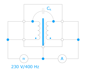
The coupling capacity represents a measure for the possible transmission of interference between the input and the output sides in cases inductive components are present, such as transformers with metallic isolation of the coils. The value of the coupling capacity should be kept as small as possible and can be influenced by design measures. The decisive influence on the determination of the coupling capacity is the selection of the applied measurement methods and measurement frequencies (despite theoretical frequency independence). In addition, for direct measurement using a C-measuring bridge, a measuring configuration using a test voltage selected to reflect orderly operation appears to make more sense:
The usual utilisation of network interference filters takes place between the network and the input of the consumer (e.g. frequency converters). 1-phase and 3-phase models are available. A network interference filter efficiently brings together the characteristic of a power reactor (see “reactors”) and that of a “passive filter for the suppression of electromagnetic interference (EMI-filters)” to make just a single filter which is very effective across a wide band. Optimal tuning of the components makes it possible to have a mains borne suppression of interference from the network frequency up to 30 MHz.
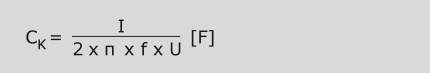
These direct current supplies are referred to among other things also as “primary switching regulators”. A frequently-applied circuit concept displays the basic function:
The intermediate circuit direct current voltage is generated directly by the rectification of the network alternating voltage. A flyback converter with a typical switching frequency >20 kHz is post-connected to the intermediate circuit. The semiconductor switch is controlled (clock-pulse controlled) by the regulator in such a way that a stable output direct current voltage ensues. The reference voltage integrated into regulator is thereby compared with the performance value of the output (generated by the voltage distributor). The regulation of the switch-on and switch-off times for the semiconductor switch takes place with these correcting variables.
The repeater ferrite must fulfil the mandatory safety-related requirements made concerning metallic isolation from the network for these kinds of circuit concepts, just as the regulator does by means of such things as optoelectronic couplers.
The advantages:
- Very high efficiency, as independent as possible of network voltage fluctuations and of the greatness of the output direct current voltage of circa 75% to over 90%
- small construction volume
- low weight
- Additional input voltage range possible
- Depending on circuit concept, AC and DC input voltage possible
The disadvantages:
- Greater circuit complexity (number of component parts, failure probability)
- Relatively long settling times, also dependent on the switching frequency
- Relatively unclean output direct current voltage (spikes, wideband spectrum)
- EMC problems caused by the clocking with a high noise level
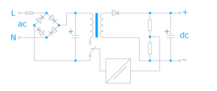
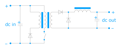
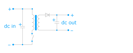
These direct current supplies are referred to among other things also as “secondary switching regulators”. A typical circuit concept displays the basic function.
The adjustment to the network takes place by means of a 50 Hz transformer with the mandatory safety-related requirements made of the metallic isolation. After rectification, an intermediate circuit voltage which is greater than the desired output direct current voltage should ensue at the charging capacitor. A step-down converter with a typical switching frequency >20 kHz is post-connected to the intermediate circuit. The semiconductor switch is controlled (clock-pulse controlled) by the regulator in such a way that a stable output direct current voltage ensues. The reference voltage integrated into regulator is thereby compared with the performance value of the output (generated by the voltage distributor). The regulation of the switch-on and switch-off times for the semiconductor switch takes place with these correcting variables.
The advantages:
- Unproblematic network separation from a safety point of view using 50 Hz transformers
- Multiple input voltages easily realised through primary taps
- Even more comprehensible circuit complexity
- Relatively high efficiency, as independent as possible of network voltage fluctuations and of the strength of the output direct current voltage of circa 70 % to 80%
The disadvantages:
- Large construction volume
- Heavy weight
- Relatively long settling times (in comparison with linearly-regulated direct current supplies) dependent on the height of the switching frequency
- Relatively uneven output direct current voltage (spikes, wideband spectrum)
- EMC problems caused by the clocking, although a relatively low noise level
These direct current supplies are often referred to as “linear regulators” or “longitudinal controllers”.
The basic structure often consists of a 50 Hz transformer which has the necessary safety-related requirements for metallic isolation from the network, rectification with filtering and a regulator. This regulator basically consists of power transistors and behaves like a changeable resistor. The electronics provides a stable output direct current voltage. The performance value of the output direct current voltage is checked at the output by means of a voltage distributor and continually compared with the reference value (reference voltage, frequently generated by a Zener diode). These two correcting variables permanantly control the regulator an determine the amount of the output direct current voltage.
The advantages:
- Unproblematic network separation from a safety point of view using 50 Hz transformers
- Multiple input voltages easily realised through primary taps
- Simple circuit conceptü Brief settling times
- Very low ripple
- Very few EMC problems
- Inexpensive concept up to circa 50 W
The disadvantages:
- Poor efficiency
- Efficiency is very dependent on the network voltage fluctuations and the size of the output direct current voltage circa 60% at 24 Vdc, 35% at 5 Vdc
- Pronounced heat buildup, particularly with output direct currents
- Large construction volume
- Heavy weight
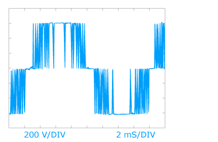
These direct current supplies are often referred to as “switching regulators”, “switched mode mains power supplies” or “switch mode power supplies”. In contrast to the linearly-regulated direct current supplies with continuous regulation of direct current voltage and direct current, these quantities are switched with clock-pulse controlled direct current supplies (chopped). As part of this concept, the power semiconductors utilised are operated exclusively as switches. Only slight switching and forward losses occur, from which the characteristically high efficiency can be deduced.
The regulation takes place either through the modification of the pulse duty ratio (switch-on time to switch-off time) with constant frequency or modification of the frequency with constant pulse duty ratio. The square wave voltage generated thereby can be transformed into practically any given voltage level and rectified. A high clock frequency in the range starting from circa 20 kHz and going up to many MHz permits the utilisation of small repeater ferrites, inductances and capacitors.
Display of the (network) transformer and of the post-connected rectifier are dispensed with in the following illustrations. The direct current voltage which ensues after rectification at the filter or charging capacitor is also often referred to as “intermediate circuit voltage”. This “intermediate circuit” usually accounts for the input with the DC-DC converters.
Based on dynamic systems behaviour, a fundamental distinction is made between two transformational converter principles:
- feed forward converter
- flyback converter
The manufacturer is required to attach the EU designation to products which fall under the authority of certain EU regulations as a sign of conformity with them. The products affected are those which are covered by the guidelines made in accordance with the “New Concept” (issued 07.05.1985) which contain requirements governing the technical quality of different products.
EU guidelines are binding legal directives of the European Union. That means that the fulfillment of these requirements is a precondition for the marketing of the products in Europe. This does not affect the rest of the world trade market. The attachment of the EU designation confirms product conformity with the corresponding fundamental requirements of all (applicable) guidelines affecting the product. As the documentation of conformity with directives, the EU designation is solely intended for monitoring government agencies. It is, however, often misinterpreted as a “Quality Seal”. Because of this, it is unfortunately often demanded in cases where there is no legal requirement for it.
For this reason, our company dispenses with any advertising display of the EU symbol in our catalogue and prospectus pages, since the placement of the EU designation on products is done solely to satisfy a legal requirement which all manufacturers and importers are obligated to adhere to.
Although the EU declaration of conformity on the part of the manufacturer is kept on file only for the purposes of the monitoring agencies (for at least 10 years following the last bringing of the product into circulation), respective copies of it can be made available to customers upon request.
Examples:
a) Modules (for circuit boards, devices, control cabinets), which as built-in components are not required to bear the EU designation sign, such as resistors, capacitors, inductance, integrated switching circuits.
b) Modules which are required to bear the EU designation sign (with housing and with protection against accidental contact), which are to be operated autonomously and/or are to ultimate consumers, such as plug-ready power supply units, battery charging sets, personal computers, testing and measuring apparatus, isolating transformers for construction sites or service, transformers for halogen lights.
The fundamental principles for EMC standardisation are generally compiled by
- CISPR, founded in 1934(International Special Committee on Radio Interference, Comité international Spécial des Perturbations Radioélectriques)
and
- IEC TC77, founded in 1974(International Electrotechnical Commission Technical Committee 77, Comité d’études 77 de la Commission Electrotechnique Internationale)
in coordination with the IEC Regulation Guide 107 (EMC-Guide to the drafting of electromagnetic compatibility publications).
The purpose of Guide 107 is to ensure that identical procedures and points of
view are applied during the course of EMC standardisation and to keep everything as conclusive as possible. Observations are carried out on line-borne and radiated phenomena occurring in the frequency range between 0 Hz and 400 GHz, in which electromagnetic compatibility is to be
achievable.
Generally speaking, four categories of EMC standards are defined, whereby each EMC standard is, as a whole, assigned to only one of the four ategories.
1. Basic publications (Basic Standards): The Basic Standards can have the status of a standard or even that of a technical report. They contain the respective measuring procedures, classification of environmental conditions and testing techniques for EMC, but no measurement limiting values for individual products or product families. Constant reference is made to the Basic Standards in the basic specifications, product family standards and product standards. It should be clear from the title alone that it is a Basic Standard (Basic Norm) which is being dealt with.
2. Basic specifications (Generic Standards): The basic specifications are to be applied to products for which neither product family standards nor product standards exist. There is always a distinction made between the environmental conditions of industry (supplied by industrial networks) and those of residential, business and trade areas and small-scale enterprises (supplied by public electricity networks). While limited number of EMC tests specify minimum interference limit values and maximum interference emission limit values, they do not address certain product characteristics.
3. Product Family Standards: The product family standards are tailored to specific product families and contain particular specifications (e.g. limit values, test design, operational criteria and criteria for complaints). Concerning measuring procedures, Basic Standards are referred to and limit values are coordinated with the basic specifications. Product family standards for EMC can exist as independent standards, but also as (autonomous) parts of standards which govern the other aspects (e.g. electrical safety) for the product family.
4. Product standards: The product family standards are intended for special products, they enjoy the highest application priority and are therefore the only ones to be applied for ensuring the EMC of the product. In terms of the inclusion of Basic Standards and basic specifications, the rules which apply to the product family standards are the same as those for the product standards.
The utilisation of passive filters for the suppression of electromagnetic interference (EMI filters) is the mains borne suppression of interference on the network in the frequency range located between 150 kHz (9 kHz)(1) and 30 MHz. Here are several lowpass principal circuits:
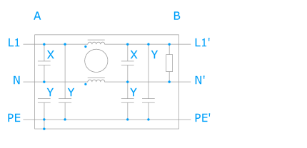
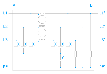
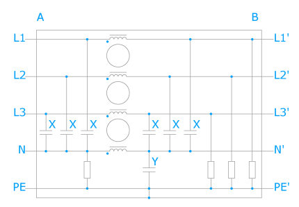
A = line B = load
Interference suppression components utilised:
- Capacitors Class Y (L-PE, N-PE)
- Capacitors Class X (L-L, L-N)
- Resistance for discharge of the capacitors
- Current-compensated magnetic core reactor
An even more efficient suppression of interference, and with it a greater insertion attenuation, is achieved when additional elements (interference suppression components) are added, thus creating multi stage constructions.
(1) not yet included as part of the EMC standardisation.
According to the definition contained in the EMC Regulation 89/336/EEC, electromagnetic compatibility is the capability of a device to be able to work
satisfactorily in the electromagnetic environment without itself causing electromagnetic interference while doing so which would be unacceptable to any of the devices, installations or systems present in this environment.
A distinction is made between
- Electromagnetic interference (EMS)
- Electromagnetic immunity (EMI)
The electromagnetic immunity is the ability of a device, an installation or a system to operate while in the presence of electromagnetic interference without
experiencing any functional impairment. The basic specification for interference immunity is
- EN 50 082-1 (Residential, business, trade areas and small-scale enterprises)
- EN 50 082-2 (Industrial area)
A large number of basic standards (IEC 61000, CISPR) and product standards are also to be taken into consideration as required.
Electromagnetic interference (emitted interference) is every kind of electromagnetic event (e.g. noise, unwanted signal), which could impair the functioning of a device, an installation or a system. The basic specification for emitted interference is
- EN 61000-6-3 (Residential, business, trade areas and small-scale enterprises)
- EN 61000-6-4 (Industrial area)
A large number of basic standards (IEC 61000, CISPR) and product standards are also to be taken into consideration as required.
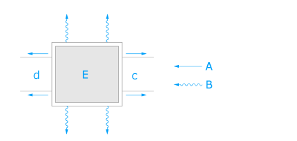
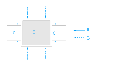
A: mains-borne disturbance
B: non-mains-borne (radiated) interference
C: out
D: in
E: resource
There are many opportunities for interference to be transmitted:
- by means of metallic contact as electrical current and voltage, carried by power mains
- as a magnetic field
- as an electrical field
- as an electromagnetic wave or radiation
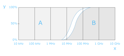
Propagation of mains borne and radiated interference generally behaves as follows:
The attenuation of interference is achieved by construction which takes EMC into consideration, involving such things as low-impedance earthing, filters, shielded lines, metallic housing and spatial clearance. The EMC measures to be carried out, however, are highly dependent on the components utilised and on the operating parameters of the system, which means that it is almost impossible to make universally valid statements.
The excess temperature is the temperature in the transformer which is created in the established operating conditions of the transformer as a result of self-heating. The maximum permitted excess temperature is calculated from the difference arising between a temperature assigned to the insulation material class and the rated ambient temperature of the transformer. Depending on the insulation material class, the possible excess temperature is also to be reduced for hot spots.
Example: Insulation material class E (120 °C), hot spot 5 °C, Rated ambient temperature 40 °C
ΔT = 120 °C - 5 °C - 40 °C = 75 °C
With the feed forward converter, energy transport takes place between the primary and the secondary circuit with a closed semiconductor switch.
Description: Energy is released at the output via the first secondary diode (in series to the secondary coil) with the semiconductor switch closed. If the semiconductor switch is open, then this diode acts as a block and the second secondary diode takes on the electrical current (magnetically stored energy) from the storage reactor and delivers it to the output. The third coil and the diode switched in series limit the voltage level at the semiconductor switch. In addition, the energy stored in the repeater ferrite during the turn-on phase is delivered back to the input source (intermediate circuit) during the turnoff phase.
Power converters and frequency converters are used nowadays with increasing frequency on the network. This leads to harmonic oscillations on the network, which causes additional attenuation, especially in the capacitors of reactive current compensation installations. Among the advantages offered by filtering circuit reactors are:
- less attenuation and no overloading of the capacitors of a reactive current compensation installation,
- the impedance behaviour of the network becomes improved.
Filtering circuit reactors require special dimensioning for safe and long-lasting operation:
- low inductance tolerance,
- linear inductance progression extending far beyond the rated electrical current and with harmonic oscillations,
- thermal design construction for continuous operation for network frequency and harmonic oscillations.
The series connection to the capacitors is carried out almost exclusively in 3-phase design, which means that it has an effect upon the entire alternating current network.
The flyback converter first stores the energy in the repeater ferrite while the semiconductor switch is closed in order to deliver it later to the secondary circuit during the blocking phase.Description: The repeater ferrite takes on energy while the semiconductor switch is closed. The diode in the secondary circuit blocks, and no energy transfer to the output takes place. The polarity is not reversed until the semiconductor switch is opened, the diode becomes conducting and the energy stored in the repeater ferrite reaches the output within the secondary circuit.
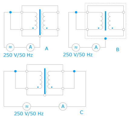
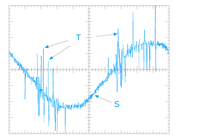
The specification of the voltage impulse attenuation in dB is a further criterion for the evaluation of the interference protection characteristics for inductive component parts such as Interference protection transformers and magnetic interference protection voltage stabilisers. Impulses of many kilovolts (kV) are not at all unknown in networks as the result of the effects of lightning. To simulate the impulse, the standard lightning surge voltage in the form of 1.2/50 µs can be applied. Here possible measurement configurations:
The input coil is the coil established for the connection with the electrical supply circuit.
There can be several coils for series and parallel connections, taps can also be present. Depending on number, amount of insulation required and percentile deviation of the taps in relation to rated input voltage, an increase in core power (structural size) may become required for the transformer.
An increase of core power is absolutely mandatory when several different input voltages are to be set up as alternatives. If for example 230 V and 400 V are called for in conjunction with unchanging rated (output) power, then the coil space required is increased by about 21 % (coil former with a single chamber). This comes about since one coil needs to be on hand for the full power of the 230 V input voltage, another one needs to be there for 230 V to 400 V. The core power of the transformer is thus to be set at a level circa 21 % higher than the rated (output) power.
Insertion attenuation represents a non-system-dependent benchmark criterion for passive filters. The measuring procedure has been standardised (Ref.: CISPR 17) and adapted from communications engineering. It describes the logarithmic ratio U1: U2 of the (interference) voltage before and after the insertion of a filter into a circuit in terms of the frequency, measured at the output.
a = 20 * Ig (U1 : U2) [dB]
If the filter is terminated on both sides with a real resistor of e.g. 50 Ω during measurement of the insertion attenuation, then one speaks of a 50 Ω insertion attenuation.
Measurement with unequal real terminating resistors (e.g. 0.1 Ω/100 Ω or 100 Ω/0.1 Ω) can also be carried out. These combinations make it possible to evaluate a filter in case of a mismatch. Even a negative insertion attenuation, meaning an (interference) voltage increase, is thereby possible.
While these measuring procedures do permit a comparison of different filters and make possible a preselection of the desired attenuation characteristics, they do not provide much information concerning the effectiveness of the filter in individual applications. The reason for this is to be found in the fact that neither the source of the interference (interference sink) nor the connected power line system exhibits a real resistor of 50 Ω. In addition to this there is the fact that the measurement of the 50 Ω insertion attenuation takes place in the small signal range (circa 1 V) and that the operating current (non-linear magnetisation characteristic curve, pre-magnetisation) is not achieved for the inductances of the filter. The interference voltage level itself, however, lies once again in the small signal range.
Proof of whether the limit values of the EMC standards (see “Electromagnetic Interference” and “Electromagnetic Interference Immunity”) can be maintained can be obtaines only by means of measurement technology as a systems test which takes into account all participating individual components.
The regulations (Ref.: VDE 0301/ HD 566S1/IEC 60085) in addition to (Ref.: VDE 0304/HD 611.1S1/IEC 60216) describe among other things the thermal resistance of electrical insulation materials. The different insulation material classes are assigned temperatures in reference to their periods of thermal resistance.
Common Insulation material classes: A (105 °C), E (120 °C), B (130 °C), F (155 °C), H (180 °C)
Unless other arrangements have been made, transformers and power reactors are designed in accordance with the specifications of the insulation material classes E or B.
The level of the insulation resistance offers information concerning the insulation capability of an electrical insulation system. For isolating and safety transformers with double or enhanced insulation (Ref.: VDE 0570/EN 61558/IEC 61558), minimum limit values apply ranging from 2 MΩ to 7 MΩ. As far as the measurement configuration used for the determination of the insulation resistance is concerned, one can proceed the same as with leakage current. One difference, however, is that a direct current voltage of 500 Vdc is put into place for testing purposes. The Insulation resistance is then computed as R = U/I.
An electrical insulation system (EIS) is an insulating arrangement made up of one or more insulation materials (electrical insulation materials) which is installed together with the associated conduction parts in one piece of electrical equipment (Ref: VDE 0302 Teil 1/ EN 60505/ IEC 60505 sowie VDE 0302 Teil 11/ EN 61857-1/IEC 61857-1). A judgement is made under thermal stresses of whether or not the combination of insulation materials is suitable for operation in the respective insulation material class.
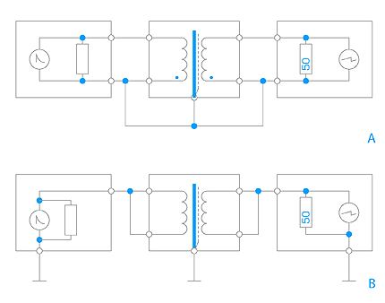
Leakage current is an unwanted flowing alternating current between electrical poles which possesses different levels of voltage potential. The maximum limit values for the leakage current are established in some regulations for installations and devices (e.g. DIN VDE 0100 maximum 0.75 mA, DIN VDE 0750 maximum 0.25 mA). Some of the possible measurement configurations are listed below (e.g. substitute leakage current measurement based upon DIN VDE 0701). The leakage current of a piece of electrical equipment ought to be small, since an additive buildup of current takes place on the mains as a result of the simultaneous operation of several devices.
A: Measurement configuration for the determination of the leakage current for devices of the protection class I
B: Measurement configuration for the determination of the leakage current for devices of the protection class II
C: Measurement configuration for the determination of the leakage current between primary and secondary
Inductive component parts generate low-band magnetic fields, called forth by the leakage fields of the magnetising procedure at the level of the operating frequency. Effects on neighbouring electrical equipment, devices, apparatus or installations cannot to be ruled out entirely. The degree of the influence is essentially dependent upon an EMC-compliant construction (earthing, shielding) of the components and on their spatial clearance from one another. For the purposes of general estimation and as an aid to project design, the following typical values can apply, based on a rated power of circa 200 VA:
| Component* (without shielding) | Stray field induction at a distance of | |
| 10 mm | 100 mm | |
| Toroidal transformer | 1,2 mT | 0,02 mT |
| EI-frame transformer | 2,2 mT | 0,04 mT |
| EI-frame reactor with air gap | 12 mT | 1,3 mT |
| Magn. voltage stabilizer | 5 mT | 0,3 mT |
| *Cover: Magnetic core induction approx. 1.2 T (1 tesla = 1 Vs/m2) at 50 Hz |
For non-critical applications, we recommend a clearance of 50 mm to 100 mm between the components and between them and the shielding (e.g. sheet metal housing). For critical applications (e.g. sensitive measuring amplifiers, digital circuits, monitors), additional EMC shielding measures or greater clearances are generally necessary. However, EMC measures to be carried out depend heavily upon the components utilised and upon the operating parameters of the system, which means that it is impossible to make statements of universal validity.
Magnet core power is the power which would be transmitted to the magnet core as a transformer with separated (spaced apart) coils. In everyday speech, the term “core power” is frequently used for “magnet core power” and “throughput power” for “rated power” in reference to auto transformers.
Auto transformers possess shared input and output coils. For this reason, there is no metallic isolation between the coils. Depending on voltage turns ratio, there is to some extent a considerable reduction of the core power in comparison with a design with separated coils.

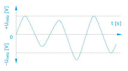
Mains interruption cause systems failures and impair the functioning of installations, computers and highly sensitive electronic consumers and equipment. Investigations in Central Europe have shown that 3/4 of all sporadically-occuring errors and faulty functioning among highly-sensitive consumers are based on defective quality of the power supply.
The most common occurrences are:
- long-term network overvoltage
- long-term network undervoltage
- interference impulses and transient
- voltage drops and voltage surges
- electrical disturbanceü short-term mains interruption
- long-term mains interruption
Mains interruptions can result from a wide variety of causes, e.g.:
- switching procedures in the mains
- long cable paths in the mains
- environmental influences, such as storms
- mains overloading
Typical causes for mains interruptions generated in-house include, for example:
- thyristor-controlled operating mechanisms
- elevators, air conditioning systems, copy machines
- motors, compensation installations
- electrical welders, large machines
- switching illumination device
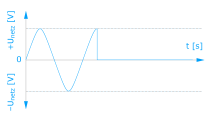
Mains voltage fails to achieve minimum levels over a long period by more than –10 % (VDE 0175/HD 472 S1/IEC 60038).Circa 20–30 % involvement in mains interruptions. Leads to non-defined operating states for the mains units of the components, caused by deficient mains stabilisation. Causes data errors.
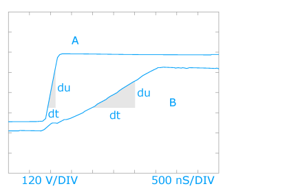
The problems connected with the operation of alternating current motors at the frequency converter are increased with the utilisation of rapidly-switching power semiconductors. The steep buildup and falloff of the voltage (edge steepness du/dt up to 12 kV/µs) causes, among other things, the following:
- Problems with the insulation strength and service life of the coil wires in the motor
- Generates harmonic oscillations of greater intensity up into the high frequency range
As a result of the utilisation of motor reactors,
- the edge steepness is reduced to circa 500 V/µs, which protects the motor
- the high-frequency harmonic oscillation share is reduced, which means that electromagnetic compatibility with other systems components is improved

Open-circuit current is the (apparent) input current of the non-loaded transformer at the rated input voltage and the rated frequency.Because of non sinusoidal shape of the curve, measurements are to be carried out using “true effect” testing equipment. The size of the open-circuit current can also vary within a production lot, mainly because of non-constant core sheet characteristics. The open-circuit current should, however, be lower than the input current at rated (output) power in order to avoid any possible overloading of the input (primary) coil of the transformer during open-circuit operation.
The open-circuit operation output voltage (Ref.: VDE 0570, EN 61558, IEC 61558) is the output voltage of the non-loaded transformer with rated input voltage and rated frequency. For safety, isolating and control transformers, the highest permissible values for deviation in terms of rated output voltage are to be observed to some extent. The respective determinations are specified in Part 2 of the Standard named above for the various transformer types.


In cases of rated (output) power levels of over 1 kVA, the short circuit voltage (as a percentage of rated input voltage) will be specified. Short circuit voltage (%), deviation (%), regulation (%) and open-circuit voltage factor (factor – 1.00 = %) can be roughly compared with one another.
A = deviation
L = open-circuit operation output voltage
B = nominal output voltage
F = factor
R = regulation
The output coil is a coil designated for connection with a distributing network, a device, a piece of equipment or another installation. There may be several coils and taps present. Depending on number and on the amount of insulation required, an increase of the core power (structural size) of the transformer could become necessary. Unless other arrangements have been made, this is the way that taps are designed for the intensity of the current at the highest voltage level and they can carry loads only in alternation.
If the full rated (output) power is to be available from every tap and/or if several output coils are desired which are not simultaneously able to carry loads or to carry changeable loads, then the need for winding space increases. The core power of the transformer is thus to be set at a level
higher than the rated (output) power.
This has to do with a stochastic or random discharge between two voltage-bearing electrodes which bridge over only a partial distance of the clearance between the electrodes. They appear first at the contact surface or also sometimes physically displaced within an insulation configuration. If this occurs in a solid insulation material, then it is referred to as an internal partial discharge (PD), the causes of which are to be found either in defective manufacturing technology or in the use of unsuitable materials. Numbered among the latter for actual insulation materials are hollow spaces, voids and non-homogeneities which cannot be ruled out to 100%.
A simplified insulation configuration between two electrodes is provided in the illustration in order to better clarify the processes which contribute to the formation of a partial discharge. The individual capacitors illustrate the course of the lines of electric flux. CF indicates the concentration of the lines of electric flux in the flaw position, C symbolises the course of the lines of electric flux from the surface of the insulating material to the walls surrounding the hollow space. If the initial voltage in this configuration crosses over the flaw position which is to be considered a voltage- dependent radio link (CF), then a voltage drop UF occurs there, which causes a change in the charge qF. The voltage leap at the electrodes caused by this can be used for an analysis of the PD activity of the insulating material.
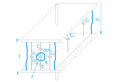
E = Electrode
I = Insulating material
F = Void
Effect:
Every discharge caused by a PD causes a weakening of the material surrounding it. Continuous PD leads to a permanent destruction processes in the insulator. When the damage reaches an advanced state it results in the loss of insulation capability. Therefore, in order to ensure a permanently reliable insulation system configuration, it must be a requirement that:
- no PD shall occur in the insulation system in connection with the maximum allowable operating voltage plus a safety margin
- PD caused by transients shall terminate automatically after cessation of the overvoltage
- PD freedom shall be designed for the maximum peak value plus a safety margin for amplitude stresses with continuously repeating voltage impulses
The previously won research results show a new way for evaluating insulation systems the low-voltage technology transformers. It is becoming possible to make more than just a vague Good/Bad statement about safe electrical separation inside a transformer – now one can also evaluate its quality, which also means a statement predicting its service life.
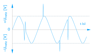
The electric supply companies (EVUs) are obliged for economic reasons to try to minimise the amount of harmonic oscillation and with it the network loads of their networks. Respective EMC Standards (Ref.: e.g. EN 61000-3-2) are either already enacted in law or are in preparation. The main goal is the minimisation of the harmonic oscillation currents while simultaneously correcting the power factor. The term “power factor” is understood to mean the relationship between the active power consumed and the apparent power of a consumer. The power factor 1 with sinusoidal current consumption yields the lowest network load.Unfortunately, direct current supplies also cause the phenomena described, among others. This is a result of the rectification of the (mains) input voltage with subsequent capacitor smoothing. If the direct current voltage falls below the peak value of the feeding alternating voltage, then the capacitor will be recharged with brief currents in the form of impulses. In this connection, it is of rather less importance whether this configuration is operated directly on the network or through the use of a pre-connected transformer:
The harmonic oscillations content can be reduced by the pre-connection of a frequency-dependent resistor (see in this connection “Power reactors”) within certain limits. However, in order to correct the power factor directly and in a way dependent upon load, an electronic control system is required which ensures that the electrical current is taken from the network in sinusoidal shape and in the same phase position to the voltage. Here is a possible circuit concept:
A semiconductor switch – controlled by the amount of the burden (load) – clocks the 50 Hz (network) input current consumed using a high switching frequency (e.g. 20 kHz) in connection with the storage reactor. This becomes “modulated” to such an extent in synchronisation with the phase position of the (network) input voltage that a power factor results which is almost 1.
It is particularly in connection with unregulated direct current supplies that it is frequently necessary to ensure that brief network interruptions in the millisecond range (e.g. caused by switching procedures) do not lead to control system errors. An additional wiring with a charging capacitor parallel to the dc output makes it possible to store energy and to release it again in the event of a brief network interruption. The capacity of the additional charging capacitor can be determined as follows:

C = Capacity of the charging capacitor (mF)
t = Power failure duration (ms)
Idc = direct current removed (A)
dUdc = Permitted direct current voltage reduction in terms of the power failure duration (V)
Example: Due to network switching procedures, network interruptions occur which are 1.5 ms long. The output voltage of an unregulated direct current supply amounts to 22 Vdc with rated direct current 3 Adc and rated (network) input voltage. How large does the additional charging capacitor selected have to be to ensure that the level does not fall below 21 Vdc?

Wiring with 4,700 µF (next highest standard value) makes it possible to have the desired network bridging here.
Note:
1. When wiring is added later, a test should be carried out to determine whether the rectifier (in the existing direct current supply) can provide the additional energy requirement in the moment of switching on without any damage.
2. In cases of high-power direct current supplies, it is often sufficient just to equip the sensitive control system part (with low current consumption) with an additional charging capacitor by means of a decoupling diode.
A side effect of wiring with a supplementary charging capacitor is also the positive effect on the ripple. In most applications, however, the advantage of a lesser ripple is much less important than the advantages of power failure bridging.
The power failure bridging time – also known as the dwell time (Ref.: VDE 0557/ EN 61204/IEC 61204) – is the time in which a regulated direct current supply is still able to supply the rated output direct current, although the (network) input voltage has been switched off. The rated output direct current voltage is hereby still within the assigned tolerance and the (network) input voltage had the assigned minimum value (network undervoltage) plus 10% prior to the switch-off.
The most efficient method is to increase the power failure bridging time in cases where the intermediate circuit charging capacitor of the regulated direct current supply (see e.g. wire diagram “Primary clock-pulse controlled direct current supplies”) exhibits a high capacity and is thus able to store a great deal of energy. The charging capacitor which is switched in parallel to the output of a regulated direct current supply can also in principle be increased in size in order to achieve a longer power failure bridging time, although this can lead to undesirable effects on the regulating characteristics of the circuit. Furthermore, it could happen that only a slow buildup of the output direct current voltage takes place after the switch-on, depending on the electronic current limitation concept selected.
Usual realisable times for a power failure bridging are 3 ms to 10 ms, or even 20 ms with greater expenditure. The utilisation of a USV (no-break power supply) is usually necessary for bridging even longer periods (e.g. for data backup protection on storage media).
These reactors are usually used in the mains in series connections to the user. Single phase and 3-phase models are available. They provide the following important safety functions:
- Attenuation of harmonic oscillation currents resulting from frequency-dependent inductive resistance
- Starting current limitation for the user and thus reduced module stress, e.g. for rectifier circuits
- Guarantee of the short circuit voltage UK of 4% to the network frequently demanded by the EVUs (electric supply companies)
Example: With rated electrical current (e.g. 4 A) and rated frequency (e.g. 50 Hz) of a reactor with UK = 4 %, 96 % of the mains voltage (3 * 384 V) is still available to the consumer (ohmic resistance) on a 3-phase network of 3 * 400 V/50 Hz. The rated voltage drop of each phase at the reactor amounts to 16 V * 1/w3 = 9.2 V and the rated inductance is calculated to
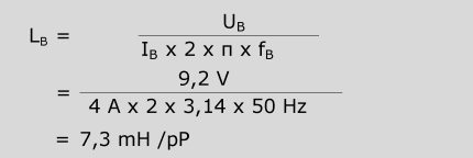
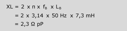
From an idealised point of view, harmonic oscillation currents are reduced in relation to fundamental oscillation (1st harmonic = 50 Hz) by the factor of the ordinal number (e.g. 3rd harmonic = 150 Hz = factor 3). However, the statements made concerning the “frequency behaviour” of reactors should be taken into account for this.
B = rated pP = per phase
A direct current supply is a static device with one or more entries and one or more exits which transforms a system of alternating voltage and alternating current and/or direct current voltage and direct current into a system with direct current voltage and direct current through electromagnetic induction, usually with different values, for the purpose of transmitting electrical energy.
Requirements
The design-related differences between direct current supplies are determined mainly by their intended utilisation. The respective requirements are set fourth in the installation and device standards (e.g. VDE 0100, VDE 0113/EN 60204/ IEC 60204, VDE 0700/EN 60335/ IEC 60335, VDE 0805/EN 60950/ IEC 60950) and in the available standards for direct current supplies for general end use (e.g. VDE 0570/EN 61558/IEC 61558, VDE 0557/EN 61204/IEC 61204).
An important selection criterion is the construction of insulation between input and output circuits, as has already been described above under “Transformers, Requirements”.
A distinction continues to be made following the conversion of alternating voltage/alternating current/AC and direct current voltage/direct current/DC:
- AC/DC converter
input alternating voltage, output direct current voltage - DC/DC converter
input direct current voltage, output direct current voltage
The stability and ripple of the output direct current voltage is a further important selection criterion. A distinction is made between
- Unregulated direct current supplies
- Regulated direct current supplies
Standards
Unless otherwise agreed upon with the ordering party, we manufacture in accordance with the latest “State of Technology” and with the following standards:
Unregulated direct current supplies
- VDE 0570: Sicherheit von Transformatoren, Netzgeräten und dergleichen Teil 1: Allgemeine Anforderungen und Prüfungen, in Verbindung mit dem jeweilig zutreffenden Teil 2.
EN 61558, IEC 61558: Safety of power transformers, power supply units and similar, Part 1: General requirements and tests, in accordance with the relevant Part 2.Regulated direct current dupplies - VDE 0570: Sicherheit von Transformatoren, Netzgeräten und dergleichen, Teil 1: Allgemeine Anforderungen und Prüfungen, in Verbindung mit dem jeweilig zu-treffenden Teil 2.
EN 61558, IEC 61558: Safety of power transformers, power supply units and similar, Part 1: General requirements and tests, in accordance with the relevant Part 2. - and/or:
VDE 0557: Stromversorgungsgeräte für Niederspannung mit Gleichstromausgang
EN 61204, IEC 61204: Low-voltage power supply devices, D. C. output – Performance characteristics and safety requirements. - and/or: VDE 0805: Safety of information technology equipment
EN 60950, IEC 60950: Safety of information technology equipment
The protection class 0, I, II or III
(Ref.: VDE 0140/EN 61140/IEC 61140) is a construction feature for the classification of electrical equipment for the purpose of security against dangerous fault or leakage currents (electrical shock), e.g.:
- Protection class I:
Device with protective conductor connection and (at least) basic insulation
- Protection class II:
Device without protective conductor connection and double or enhanced insulation
- Protection class III:
Device supplied with SELV (Safety Extra-Low Voltage) and in which no voltages higher than the SELV are generated.
Electrical equipment intended for installation in devices have no safety class and can only be “prepared for” one of these. Electrical equipment which has been prepared for utilisation in protection class II devices can also be utilised in protection class I devices.
Specification of the type of protection (Ref.: DIN VDE 0470, EN 60 529, IEC 60529) describes the protection of electrical equipment by means of housing, covers, enclosures and similar.
The type of protection is specified by letter symbols (IP Code), whereby the first code number (0 to 6) offers information concerning protection against contact and against the penetration of foreign objects. The second code number (0 to 8) provides information about protection against the water penetration.
Common types of protection in use:
- IP 00
No special protection against accidental contact or against the penetration of foreign objects. No special protection against water. Constructions of the “open design type” are manufactured for the IP 00 type of protection.
- IP 20
Protection against contact and against the penetration of solid foreign objects larger than ø 12 mm. No special protection against water.
- IP 23
Protection against contact and against the penetration of solid foreign objects larger than ø 12 mm. Protection against water spray falling at any angle of up to 60° to the vertical, so that such jets will have no damaging effects. - IP 40
Protection against contact and against the penetration of solid foreign objects larger than ø 1 mm. No special protection against water. - IP 44
Protection against contact and against the penetration of solid foreign objects larger than ø 1 mm. Protection against water spray so that no spray hitting the equipment from any direction will have any damaging effect. - IP 54
Complete protection against contact. Protection against damaging dust deposits. While dust penetration is not completely prevented, the dust which does enter may not amount to quantities which will impair working procedures. Protection against water spray, so that no spray hitting the equipment from any direction will have any damaging effect.
- IP 65
Complete protection against contact. Protection against dust penetration. Protection against water spray. Protection against water jets from spray nozzles directed at the equipment from all directions to the extent that no spray will have any damaging effect.
- IP 67
Complete protection against contact. Protection against the dust penetration. Protection against the effects of temporary immersion in water. Water shall not be permitted to penetrate in a quantity which will would cause damaging effects when the housing is temporarily immersed in water under standardised pressure and time conditions.
Note: The specification of the type of protection refers to the condition at the time of delivery and to the established or usual method of setting up the equipment. The type of protection can change as the result of a different setup or installation method.
The rated electrical current (Ref.: VDE 0565 Part 3/EN 60939/IEC 60939) is the greatest effective operating current at rated frequency or the greatest operating direct current with which a filter may be operated continuously at its rated temperature (1). It is specified by the manufacturer for one or
both of the following conditions:
a) open-air (lRO)
b) with a specified heat sink (lRH)
(1)Addition: rated ambient temperature Unless other arrangements have been made, filters will be designed accordingly, mounted on a wooden foundation in position for use, in accordance with Condition b).
The rated primary current of a transformer comes into force with rated primary voltage, rated frequency and orderly operation with rated power load. If the rated primary current is not known or cannot be determined using measurement technology, then an approximate determination can take place as follows:
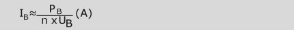
PB = rated (secondary) power (VA) divided by 3 in the case of alternating current
UB = rated primary voltage (V) with alternating current combined voltage
L – N
n = efficiency of the transformer
typically 0.94 with 3,150 VA
typically 0.95 with 5,000 VA
typically 0.96 with 8,000 VA
Calculation of the peak value of the rated primary current yields:

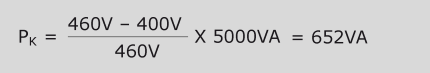
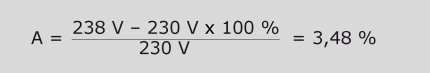
The rated input voltage range (Ref.: VDE 0570, EN 61558, IEC 61558) is the input voltage range assigned to the transformer, as expressed in its upper and ower limits. Unless other arrangements have been made, the upper limit is equivalent to 1.10 times the value of the rated input voltage with which the transformer can be continuously operated without suffering any damage. The lower limit is non-critical. It is nevertheless to be noted that the internal resistance (UK) of the transformer can increase as a result of the reduced magnetic flux through the core. The prerequisite for a description of the limit values is the transformer load at rated (output) power, expressed as the ohmic or active resistance load.
In cases where the transformer is connected to rated input voltage, in the presence of rated frequency and loading with an impedance (which, in connection with rated output voltage and by using the rated power factor for alternating current, results in rated power) the output voltage may not deviate from its rated value by more than the following:
- 10 % for the output voltage of unconditionally short circuit-proof
transformers with a rated output voltage, - 10 % for the highest output voltage of unconditionally short circuit-proof transformers with more than one rated output voltage,
- 15 % for the other output voltages of unconditionally short circuit-proof transformers with more than one rated output voltage,
- 5 % for the output voltages of other transformers.
The percentage values listed above are increased by 5 for transformers with
rectifiers.
Measurement is carried out after warmedup operating temperature has been reached (equilibrium state) and (unless other arrangements have been made) at rated ambient temperature and rated (output) impedance for which the rated power factor = 1.
For transformers with several output coils, each coil group will be simultaneously loaded, unless some other arrangement has been
established.
For transformers with attached rectifiers, the output voltage will be measured at the terminations of the direct current circuit with a voltage measuring device as an arithmetic mean value, insofar as the voltage is not expressly specified as an effective value.
The rated power (Ref.: VDE 0570, EN 61558, IEC 61558) is the product arising from rated output voltage and rated output current or, in cases of multiphase transformers, the product times √n, where n is the total number of the phases.
Note: When single-phase transformers (e.g. control transformers) are being connected to two external conductors of a three-phase network, the number of phases is to be set to 1 for the rated power of the transformer.
In cases where the transformer has more than one output coil or an output coil with taps, the rated power is the sum of the products of rated output voltage and rated output current of all circuits which can be loaded simultaneously.
A reactor is a device which is made up of one or several coils with a frequency-dependent impedance and which works in accordance with the principle of self-induction, whereby a magnetising electrical current generates a magnetic field which is directed through a magnetically-charged core or through air (Ref.: Ref.: VDE 0570 Teil 2–20/IEN 61558-2-20/IEC 61558-2-20).
The general statements already made concerning such things as protection class, type of protection, insulation material class, rated ambient temperature and (to the extent applicable) transformers also apply to reactors.
Usually, and unless otherwise agreed upon with the ordering party, reactors will be manufactured with basic insulation between voltage-bearing parts and the core. As a result of the laws of physics, the presence of at least one air gap in reactors causes an operating frequency magnetic leakage field which cannot be ignored and an acoustic noise development which corresponds to twice the operating frequency.
There is a need for providing sufficient clearance to neighbouring electrical equipment and ferromagnetic materials (e.g. steel switch cabinet).
An important criterion for dimensioning is utilisation of reactors provided for in the low-band range, e.g. as:
- Power reactor
- Smoothing/commutating reactor
- Detuned reactor
- Motor reactor
- Motor filter
- Sine filter
Unless otherwise agreed upon with the ordering party, we manufacture in accordance with the latest “State of Technology” and with the following standards:
VDE 0570: Sicherheit von Transformatoren, Netzgeräten und dergleichen, Teil 1: Allgemeine Anforderungen und Prüfungen, Teil 2–20: Besondere Anforderungen an Kleindrosseln
EN 61558, IEC 61558: Safety of power transformers, power supply units and similar, Part 1: General requirements and tests, Parts 2–20: Particular requirements for small reactors.
Typical use of reactors within the scope of the standard
| Laminated (lamellar) cores | Iron power cores | Ferrite cores |
| <3 kHz* | <250 kHz* | <1 MHz |
| Smoothing/ Commutating reactor | Smoothing/ Commutating reactor | Smoothing/ Commutating reactor |
| Power reactor | Motor reactor | Motor reactor |
| Detuned reactor | Motor filter | Motor filter |
| Motor reactor | Sine filter | Sine filter |
| Motor filter | ||
| Sine filter | ||
| *Still effective at sinusoidal frequencies |
Conventional switch mode power supplies typically set current limiting at 1.1 times the rated output current. The use of these power supplies becomes very problematic as soon as heavystarting loads are switched in, since these power supplies are not able to make available suffi cient current for them. The PowerVision series has power reserves which can make available twice the current at constant voltage for at least 4 seconds. This makes for reliable operation and removes the need for expensive overdimensioning of switch mode power supplies.
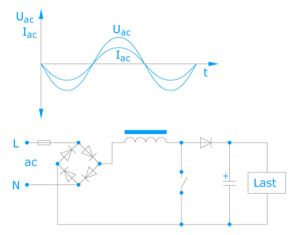
Regulated direct current supplies possess electronic control circuits in order to maintain the output direct current voltage, or in special cases the output direct current, as constant as possible at a particular value. Influences such as (network) input voltage fluctuations or different output loads are electronically adjusted to maximum power in the assigned functional area.
The ripple of the output direct current voltage falls in the millivolt range and is dependent to the greatest extent on the load at the output. The constancy of the output direct current voltage is to be found in the range of 1% to 3%, depending on the circuit concept. In addition, regulated direct current supplies often also offer the advantage of an electronic current limitation. This can protect not only the connected user but also the direct current supply itself in case of overloading.
From a conceptual point of view, a distinction is made between:
- Direct current supplies with linear regulation
- Direct current supplies with pulsed regulation
Unregulated direct current supplies:
The ripple (Ref.: DIN 41 755-1) is the ratio of the effective value of the superimposed alternating voltage Us to the value of the arithmetical direct current voltage Ud and is specified in percentage form:
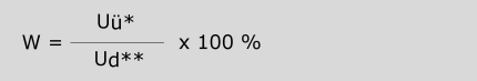
*eff only ac
**arithm.
The test setup is identical for single-phase
and 3-phase direct current supplies:
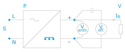
P = direct current power supply
S = mains
B = Rated
V = User
Unless otherwise specified, the specification of the ripple refers to the load with rated direct current and an actual load impedance.
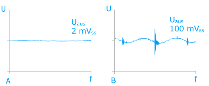
Regulated direct current supplies:
In contrast to unregulated direct current supplies with ripples in the volt range, regulated direct current supplies possess only very low levels of ripple. For that reason, this is no longer given as a percentile value but rather as an absolute voltage value in mVss (millivolt peak-peak), it is furthermore maximally independent of the level of the output direct current in the assigned functional area. Non-sinusoidal ripples (e.g. spikes) which exhibit wide-band frequency behaviour can occur as the result of regulating and switching procedures within the regulated direct current supply.
Qualitative differences in the ripple of the output direct current voltage also exist between the linearly-regulated and the clock-pulse controlled direct current supplies.
If the important thing is a supply direct current voltage which is as “clean” as possible, as is the case for example in measurement and regulation technology, then one should regard linearly-regulated direct current supply as the preferable alternative.
Transformers are divided up according to their type of short-circuit-proofness (Ref.: VDE 0570, EN 61558, IEC 61558):
A short circuit-proof transformer is a transformer for which the temperature does not exceed established limit values when the transformer is overloaded or short-circuited and which continues to fulfil all the requirements of the Standard listed above once the overload or the short circuit has been eliminated.
- An unconditionally short circuit-proof transformer is a short circuit-proof transformer without a protective device for which the temperature does not exceed the established temperature limit values in cases of overload or short circuits which can continue to be operated after the overload or the short-circuit has been eliminated. Note: Due to physical limitations, this kind of transformer permits only structural designs with low levels of rated power of up to circa 4 VA. The open-circuit voltage factor can thereby take on a value of up to 2.00. The shape of the curve of the output voltage can deviate from the sinusoidal form. It is not mandatory that unconditionally short circuit-proof transformers need be permanently short circuit-proof.
- A conditionally short circuit-proof transformer is a short circuit-proof transformer with a built-in protective device, which opens the electrical circuit or limits the electricity in the input or output circuit when the transformer is overloaded or short-circuited. Note: Examples of protective devices are fuses, overload releases, temperature fuses, automatic and non-automatic resetting temperature limiters, posistors and automatic mechanically-triggered protective switches.
A non-short circuit-proof transformer is a transformer which is intended to be protected against excessive temperatures by means of a protective device which is not built into the transformer.
Note: Unless other arrangements have been made, the ordering party is responsible for taking measures to protect the transformer.
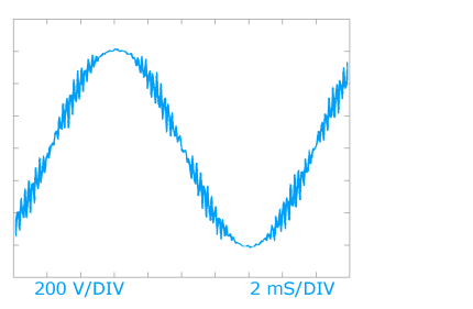
The utilisation of the sine filter extends itself to include the mains borne suppression of interference, from the frequency converter output to the shielded motor feed line with the alternating current motor attached to it, for clock frequencies from circa 500 Hz and higher.
The sine filter achieves a very high filtering effect as a result of its recise low-pass tuning to the clock frequency of the frequency converter. The wanted signal (the motor operation frequency) up to circa 120 Hz passes the sine filter with only a slight effective voltage drop, while the clock frequency (typically 8 kHz to 10 kHz) is already being reduced by circa 90 %.
Harmonic oscillations of the clock frequency are filtered out almost completely.
The special andvantages in summary:
- very high filtering effect throughprecise low-pass tuning
- practically the only edge steepness of the output voltage still remaining is that which is usual for mains
- clock frequency and harmonic oscillation of the frequency converter output voltage become severely attenuated
- long shielded motor feed line possible
- low-noise motor operation through high attenuation of the clock frequency
- reduction of leakage currents
These reactors are often utilised as storage reactors for electrical energy in direct current circuits. The core is thereby often biased with a direct current, which is either superimposed upon an alternating current characterised by the most eccentric curve progressions and frequencies or used for current direction changes (commutation). Dimensioning is highly dependent on circuits and applications.
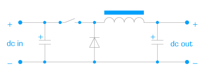
The step-down converter is able to transform a greater input direct current voltage into a smaller output direct current voltage (with correspondingly greater output direct current). Description: With the semiconductor switch closed, electrical current flows through the reactor to the output. One part of the current is transformed in the reactor into magnetic energy which is transformed back into electrical energy during the blocking phase (with open semiconductor switch). The polarity at the reactor reverses itself so that the current can flow through a diode to the output. The output direct current voltage is thereby always smaller than the input direct current voltage.
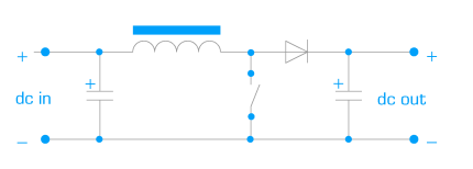
With the step-up converter it is possible to transform the input direct current voltage into a greater output direct current voltage (with correspondingly reduced output direct current).
Description: When the semiconductor switch is open, current flows through the reactor and the diode switched in feed-through to the output. When the semiconductor switch is closed, electrical
energy is transformed into magnetic energy in the reactor and stored. The diode thereby prevents the short-circuiting of the output. When the semiconductor switch is open, the magnetic energy is transformed back again
into electrical energy and a direct current voltage builds up in series to the output. The output direct current voltage is thus always larger than the input direct current voltage.
The test class indicates climate category (Ref.: DIN EN 60068/EN 60068/ IEC 60068) as the key to the designation of the climatic usability of component parts.
Example:
25/085/21 25 = –25 °C, Test A: coldness, 085 = + 85 °C, Test B:
dry heat,
21 = 21 days, Test Ca: moist heat constant
The individual tests are defined in different parts of the standard.
In automation technology, the system availability rates required today are generating increased overheads with regard to protection devices for 24 V load circuits. Previously, it was not possible to shut down faulty current paths selectively using conventional miniature circuit breakers, since the required high tripping current could not be provided by the switch mode power supplies. With its stabilised switch mode power supplies, BLOCK can provide a solution offering up to 60 A in excess of the rated current in the event of a short circuit. The proven short circuit and line protection provided by cost-effective miniature circuit breakers is also suitable for use with switch mode power supplies.
A transformer is a static device with two or more coils which transforms a system of alternating voltage and alternating current through electromagnetic induction, usually with different values but the same frequency, for the purpose of transmitting electrical energy (Ref: VDE 0570, IEV 421-01-01).
Requirements
The design-related differences between transformers are generally determined by their intended utilisation. Respective requirements are established in the installation and device standards (e.g. VDE 0100, VDE 0113/EN 60204/ IEC 60204, VDE 0700/EN 60335/ IEC 60335, VDE 0805/EN 60950/ IEC 60950) and in the transformer standards (e.g. VDE 0570/EN 61558/ IEC 61558).
An important selection criterion is the insulation construction between input and output electrical circuits:
Transformers with double or enhanced insulation
- Safety transformers (for the safety measure of safety extra-low voltage)
- Isolating transformers (for the safety measure of protective separation)
Transformes with basic insulation
- Control transformers (for the safety measure of protective earthing)
- Mains transformers with separated coils, general
Transformers without insulation (no metallic isolation) between input and output circuits
- Auto transformers
Standards
Unless otherwise agreed upon with the ordering party, we manufacture in accordance with the latest “State of Technology” and with the following standards:
VDE 0570: Safety of transformers, power units and similar EN 61558, IEC 61558: Safety of power transformers, power supply units and similar.
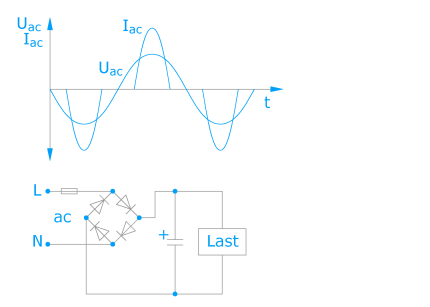
With unregulated direct current supplies, the output direct current voltage is not regulated to a specific value but instead changes in value in a way dependent on the fluctuation of the (network) input voltage and on the load.
The ripple falls in the volt range and can be dependent on the load. The specification of the ripple is usually made in the form of a percentage, proportional to the height of the output direct current voltage.
Particularly because of their construction, which is robust, uncomplicated, limited to the essentials and designed for long service life, unregulated direct current supplies are often preferred.
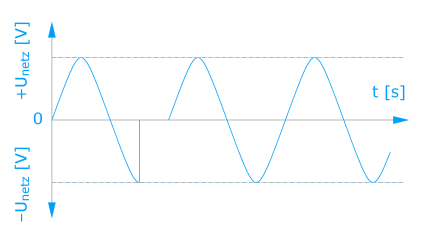
Short-term (up to circa 10 ms) interruption of the mains voltage through short-circuit in neighbouring networks or by startup of large electrical machines.
Circa 8–10 % involvement in mains interruptions. Leads to non-defined operating states for the mains units of the components, particularly those with insufficient mains bridging. Causes data errors.
The voltage range has been assigned to the filter and it is expressed in terms of the upper and lower limits within which the filter is permitted to be placed in continuous operation. Whereas it is true that the lower limit is generally non-critical, the upper limit is determined by the insulation system and the dielectric strength, e.g. of the capacitors.
In a departure from the otherwise usual standard norm-oriented allocation of voltages for electrical equipment, here the upper limit will be marked by the rated voltage of the filter, unless labelled otherwise.
In passive filters for the suppression of electromagnetic interference (Ref.: VDE 0565 Part 3/EN 60939/IEC 60939), designed essentially for the operation of mains alternating voltage, the capacitors need to fulfil the requirements of Class X or Y (depending on the position of the circuit).
Class X capacitors are catagorised according to the peak voltages of impulses superimposed on the mains alternating voltage to which they are exposed.
The switching of Class X capacitors takes place, depending on application, L-L and L-N.
XtraDenseFill from BLOCK, a casting technique delivering laser-precise and cavity-free encapsulation of the transformer’s whole internal structure via high vacuum and pressure phases. Creepage and clearance are sharply reduced and the electrical equipment enjoys long-term protection from corrosion, while the high degree of insulation permits a more compact design.
In passive filters for the suppression of electromagnetic interference (Ref.: VDE 0565 Part 3/EN 60939/ IEC 60939), designed essentially for the operation of mains alternating voltage, the capacitors need to fulfil the requirements of Class X or Y (depending on the position of the circuit).
Class Y capacitors are suitable for applications where the failure of the capacitor could lead to a dangerous electrical shock. A failure of the Y-capacitor resulting from a short circuit or a disruptive breakdown is thus prevented from occurring during the course of orderly use.
The switching of Class Y capacitors takes place to earth (PE) in relation to the application.
| Subclass | Type of bridged insulation | Rated voltage range | Peak value for surge voltage |
| Y1 | Double or reinforced insulation | ≤500 V | 8,0 kV |
| Y2 | Basic insulation or additional insulation | ≥150 V, ≤300 V | 5,0 kV |
| Y3 | Basic insulation or additional insulation | ≥150 V, ≤250 V | – |
| Y4 | Basic insulation or additional insulation | <150 V | 2,5 kV |