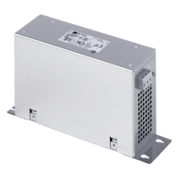
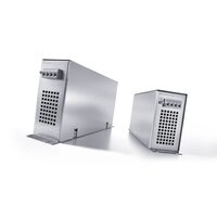
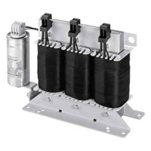
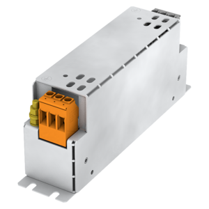
All-pole sine filter
SFA 400/40
Characteristics
Benefits
› Prevention of overvoltages on the motor
› Long cable lengths possible
› Reduction in motor noise
› Minimisation of bearing currents
› Minimisation of leakage currents (is beneficial in the event of incorrect RCD tripping)
› Reduction in line-borne and field-borne emitted interference: can be omitted from shielded cables, where necessary
› Reduction of motor losses
| Product | All-pole sine filter |
| Order number | SFA 400/40 |
| Series | SFA |
| Inductance | 3x 1 mH |
| Rated current | 3x 40 Aac |
| Linear current | 3x 60 Aac |
| Rated voltage range | 0 V to 480 V |
| Rated voltage | 400 V |
| Phases | 3 |
| Frequency range | 5 Hz to 60 Hz |
| Switching frequency range | to 16 kHz |
| Motor or converter power | 18.5 kW / 24.81 HP |
| EN Insulation class | H (180°C) |
| UL Insulation class | class 180 |
| Duty Cycle | 100 % |
| Power loss | 331.00 W |
| Wire material | Copper |
General
| Duty Cycle | 100 % |
| Cooling type | AN |
| Switching group | III0 |
Environment
| Ambient temperature | -10 °C to 45 °C / 14 °F to 113 °F |
| Max. installation height | 1,000 m / 3,281 ft |
Protection and Safety
| Protection type | IP 20 |
| Protection class (prepared) | I |
| Degree of contamination | 2 |
Electrical Connections
| Input terminal | Screw terminal |
| Output terminal | Screw terminal |
| Terminal PE | Bolt connection |
Size and Weight
| Width | 450 mm / 17.72 in |
| Height | 250 mm / 9.84 in |
| Depth | 310 mm / 12.2 in |
| Weight | 34 kg / 74.957 lbs |
| Low Voltage Directive | EN 61558-2-20 |
| RoHS compliant | EN IEC 63000 |
| Approval cURus - Recognized | UL 508; CSA 22.2 |


